Adam
wrote:
"Common
wisdom says that a ram air duct facing into the slipstream
boosts
MP, but we already have two big scoops, namely the cooling inlets!
Pressure
rise from a ram air duct should be nearly identical to the air
pressure
inside the cowl. Anyone have any thoughts?"
Indeed
I do. You are correct. A bit of care is needed, however.
My
Lancair IV mounts an IO-550 and so has the same induction air problems/opportunities
as the Legacy. I did not much care for the factory Legacy/ES induction
"ram air" system because of the flow blockage, small tube size, and poor
inlet flow coefficient arising from the sharp-edged angle-cut aluminium tube.
And it costs a lot.
But
the concept of collecting air from inside the plenum is sound - if one makes
sure the air inducted is cool and the pressure recovery into the cowl is
acceptably high, giving a bit of free horsepower from the recovery of ram
pressure.
Many
measurements show about 20F rise in air temperature in the upper cowl which can
cut HP is inducted into the engine. It is incorrect to attribute this to
ram air heating. The same ram air and friction effects create a similar
temperature rise on the OAT sensor. The temperature rise inside the top
of the cowl is in addition to the ram air compression effect.
So
what is heating the air?
It
is the air whipping through the inlets, then passing across the tops of the
fins of the front cylinder heads without going downward past the rest of the
head. A portion of the cooling air passes over the top of the front
heads, is heated modestly, and then flows back and mixes with the balance of
airflow. This then finds it way down through fins (and leaks) into the
lower cowl driven by the pressure difference between the top and bottom of the
engine. One has to be careful to avoid prematurely heating the air, and
then sucking it into the engine. Twenty degrees temperature rise causes about
3.5-4% loss in horsepower, about the same losing an inch of manifold pressure.
I
built my own induction system out of fibreglass patterned on the factory
layout, but including some improvements. Features include:
1)
Air filter for ground and low level operation.
2)
A large flapper valve that directs air either from the air filter or the
unfiltered inlet. No screws are used to hold the flapper onto the
shaft. Rather it is bonded in place and wrapped with 3 BID. A micro
switch indicates if the valve is cracked open bypassing the air filter.
3)
A larger, shorter unfiltered air inlet. The cross sectional area is about
1.5 times that of the throttle body so velocity is lower and friction losses
cut by more than half. The inlet tapers and includes a small bell mouth opening
(not much room in there) to improve the inlet flow coefficient. I set the
inlet off to the side of the cowl inlet stream so as to not block the flow from
the cowl inlet and to minimize water, bug, and bird entry to the engine.
Referring
to Chris Z's excellent article in Sport Aviation referenced by Scott, I
subscribe to the external deceleration theory of cowl inlet design with most of
the flow slowing occurring in front of the inlet where the deceleration process
is frictionless. I have sized the inlets (6 inch diameter) so that at
high cruise the inlet velocity through the cowl opening is 40% of the free stream
velocity. This means that 86% of the free stream ram pressure is present
at the inlet plane, and it is up to me to get as much of the remaining 14% as I
can after the flow enters the plenum.
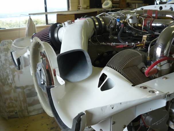
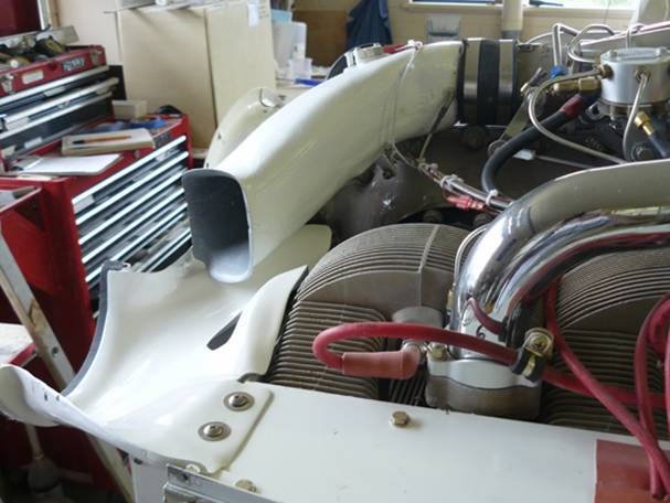
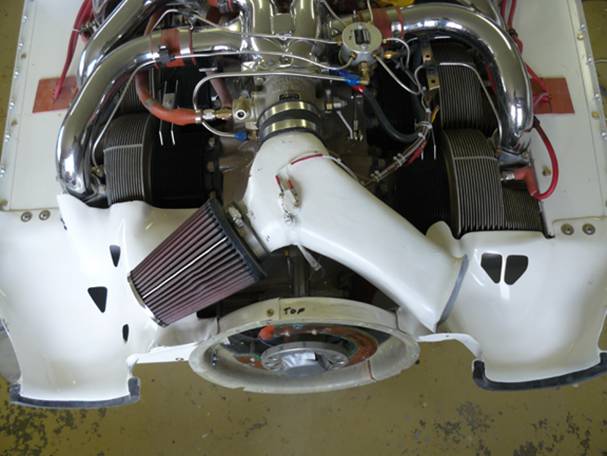
Photos
are shown below. The part was made from a foam master which was then
covered with fibreglass, slit in half horizontally, foam chewed out, cleaned
up, and then bonded together with the flapper valve captured inside. The
flapper valve shaft is made from 1/4 inch hydraulic tubing. It took a lot
of fussing to get the flapper valve to seal without leakage (no obvious
daylight when the flapper is seated).
Fred
Moreno