Thanks for the quick responses! I think we have
the basis for a good, educational discussion and hopefully can carry these
forward to a final set of recommendations. With regard to specific
comments:
Hamid wrote: I think the importance of good
workmanship and proper component selection has not been emphasized enough.
I agree entirely. If you put a $4 Radio Shack toggle
switch in to control a critical system, I think you are playing Russian Roulette.
I recall years ago talking to the shop manager at Lancair Avionics (several shop managers ago).
He had tested many rocker switches, and found most
to be not especially reliable.
Can some of you contribute suggestions on what constitutes a
satisfactory component (like the diode mentioned) for various applications?
Can we compile some suggested work standards for the electrical work in our
airplanes? Many standards exist. It would be
great if they could be distilled by those who work with these standards every
day, and assembled in one place for all of us to reference. Regarding the
question of panel switches, I followed Brent Regan’s lead and put in high quality,
environmentally sealed Honeywell/Microswitch sealed toggle switches. (Eaton
makes a similar line.) These are qualified for use in tanks, Humvees and
other vehicles operating in awful environments. Not cheap, but since
switches represent potential single point failures, I believe their selection
is wise.
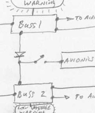
Hamid also wrote: Looking over your design, I see
one issue: Will the bus 1 to bus 2 diode keep you from reliably getting the low
voltage warning on bus 2?
Beats me, Hamid, I am just a dumb mechanical engineer.
What do your think, and what would you recommend?
Also, to all reviewing my dodgy sketch, you missed that I forgot to
insert the second diode to feed the avionics bus. See the missing diode
now? (My sketching workmanship standards need improvement.)
John wrote: If one uses the B&C voltage
regulators and the circuit therein to power a caution lamp, it would be
adequate to detect a pending low voltage on a buss. No? I'm not sure how the
Chelton gauges are wired, but they should provide voltage readouts from the two
busses, and probably current as well.
Sounds right to me, John, but I am not specifically familiar
with the B and C hardware and not qualified to evaluate it. I can tell
you what I have done. Based on recommendations received, when I upgraded
my early generation (circa 1999) Chelton hardware I tossed the EAU (engine
monitoring unit) and purchased an Electronics International MVP-50. Among
many other things, I have it configured
to monitor electrical load on both the A and B buss (amperes being drawn by the
aircraft in each system) and voltage levels on each buss. The unit
permits one to set trip levels for alarm, and the alarm is both audible and
visible. As long as the cross feed is not engaged, failure of one
alternator should result in low bus voltage and an alarm. But because I
have one little alternator and one big one, the subsequent response strategy
and load shedding depends on which alternator continues to operate. Once
I understand the fault and shed load, I will head for the ground. Note
that Columbia (and probably Cirrus) have two big
alternators.
John also wrote: One philosophical slant for me is
the use of the essential and avionics busses. They complicate the design and
increase the parts count, with their consequent effect on reliability. With a
reliable crossfeed contactor, you can have the same benefits of both of these
busses. The only thing for the pilot would be to manually reduce the electrical
load as required.
I understand your point, but suggest you consider the
following: What about the case of a cross feed contactor (or its switch or its
wiring to and from the switch or contactor attachments points….)
failing? A single point failure and poof- benefits evaporate. Would
you test the cross feed system at each run up to make sure it works? Even
if it does, a subsequent single point failure in the cross feed hardware, and
you have a problem. Consider also a bad short on one buss that takes it
off line. If you hit the cross feed as your first response you might
bring down the second buss as it leaps into the short circuit. Now the
airplane is dark and everything turns off. Oops. Consider this and
other possible failure modes. A complete “failure modes and effects
analysis” (FMEA) considers literally hundreds of combinations and
permutations of this type. Today it is done for FAR 23
certification. Most of us are not capable of doing such a thorough
job. So we should steal good designs from others if we are confident that
they are “better.”
Scott (and via Scott, Klaus) wrote lots of good stuff
including:
- It was reported
on the Lancair Mail List that Light Speed Engineering is no longer shipping/selling
dual ignition systems and only recommends a single system with a mag
backup because of too many experimental aircraft's unreliable electrical systems. To which Klaus
replied: There was a concern for a
while when we had a few sensor failures on the Continentals used on
Lancairs. The engine builder would set up the proper clearance per our
instructions, test run the engine and deliver it. The proud owner would
then install his own baffling between the case and our mounting bracket.
This would reduce the clearance to the point that the sensors could get
damaged.
I made an assumption as
to the cause of the caution (faulty electrical systems). I have to remind
myself how to spell ASS-U-ME. L
I am pleased that the problem has been isolated and corrected. Apparently
my Continental engine was caught in this cautionary period, and the engine
builder put on one mag and one Lightspeed ignition system. Now my engine
is making its way across the Pacific this way. Alas.
- Elder* Cessna
aircraft (I have some experience) use crappy components and connectors and
are frequently full of architecture and design shortcuts used to save
MONEY, not lives.
Absolutely correct, in
my direct experience. I could not believe the crap that Cessna put in my
brand new TR-182 when I bought it new in 1979. That includes switches,
circuit breakers, and other important electrical components.
- Sorry, I cannot
trust that the FAA knows any better
than an experimental aircraft builder that actually built his/her airplane
and studied available information on how-to-do-it.
Ah, Scott, you are being
cynical, but your cynicism is not misplaced. I agree that a builder familiar
with the topic should be able to build an electrical system equal to or better
than that specified by the FAA. But I am a little familiar with some
current certification processes via the CAA (Australia’s
equivalent to the FAA). CAA follows FAA on FAR 23, and in my recent
discussions with CAA I learned about requirements that manufacturers present a
quantitative safety case that subjects system designs to thorough data validation
and mathematical analysis. This is a post “elder Cessna” phenomenon,
and probably more than we as homebuilders can hope to achieve.
I merely suggest that FAA-approved
designs for MODERN aircraft provide a good STARTING point. If you are
limiting yourself to day VFR, your standards can (should) be relaxed. But
since some of us are apparently flying night, IFR, single pilot, over the
mountains at high altitude, I suggest we get the best input we can
obtain. Hence my call for an exchange of thoughts and preparation of some
recommendations and example workmanship standards that can be used by all to
improve the quality of our projects.
- One of the things
the builder cannot fix with hardware is the loss of life from serious
lapses of judgment, training and knowledge in the other
single-point failure, the pilot.
Excellent point. We should ever lose sight of the fact that
most of the time pilots kill pilots, not airplanes.
Let the adventure continue!
Fred Moreno
AKA Captain Tuna, Chicken of the Skies