|
|
From: "Vision micro" <vision_micro@hotmail.com>
Scott,
There should be no effect on the EGT/CHT, however in some cases, depending on transmitter com cable routing etc, especially with composite airframes, there may be RFI strength sufficient to affect the OAT/CAT/OIL probes. This effect is quite dependent on how the transmitted energy propagates through the airframe and how the wiring happens to route through the aircraft etc. For example, some builders report problems with autopilots (altitude hold etc.) when 'keying the mike'. Since our oil and air temp probes use the same sensor technology, both are affected in a similar manner. The software averages the values at different rates (oil temp is the longest) and hence it takes a while to return to its previous value once the mike is 'unkeyed'. (Note that no damage will occur to the oil & air temp probes during this event). We are working towards a good overall solution. These are some of our short term ideas in which to try and protect the probes against this high energy level for these aircraft.
We have found that evaluating and possibly re-routing com cables, eliminating unshielded wires to the sensor and/or twisting the wires going into the sensor as best as practical and even adding a ferrite filter before the sensor will often eliminate or reduce this effect. Again, it is very dependent on the application. Some or all of these steps can be applied depending on the intensity of your aircraft's' radiated energy:
*****NOTE **** The shielding for the Oil temp, OAT, and CAT should NOT be connected to the black wire of the probe. Before you go through the following steps that are listed below, check and make sure the shield is not on J4-2, J4-4, and J4-6. If it is connected remove it and see if your problem goes away. If the problem still exists then perform the following steps
1) Connect the SHIELD wire of the Oil Temp Transducer cable (at the engine and DPU end of the harness) to engine ground. IMPORTANT: Insure the engine is VERY well grounded.
2) Gently twist the exposed RED & BLACK wires that go into the sensor to form a twist every 1/2 to 3/4 inch or so. You probably will need to disconnect the harness to perform this.
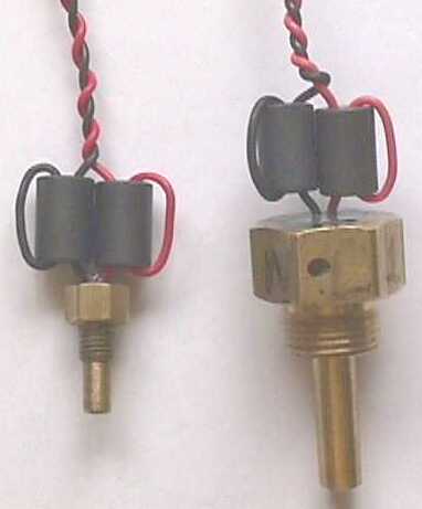
3) Place RF suppressing 'ferrite beads' over the red & black wires. (un-twist wires if already twisted, apply beads and then retwist.)
Slide the beads down the wires so they are right next to the sensor housing and then loop the wire back through the bead and twist the again. See the attached picture of temp transducers with Ferrite beads Digikey# 240-2067-ND. Put some heatshrink over the whole ferrite bead assembly and make sure the connector end is supported so that the extra weight wont cause the wires to break
4) Place foil shielding over the RED & BLACK wires that are outside of the shielded cable and connect the foil to ground.
Suppressing RF fields is very dependent on many factors, so tends to be a bit of trial and error. The main idea in all of this is to prevent (or reduce) the high RF energy from being conducted inside the sensor via the wires.
Best Regards
David McCluskey
Technical Support
Vision Microsystems
4151 Mitchell Way
Bellingham, WA 98226
www.visionmicrosystems.com
Temp_with_Ferrite_beads_Digikey.jpg
|
|