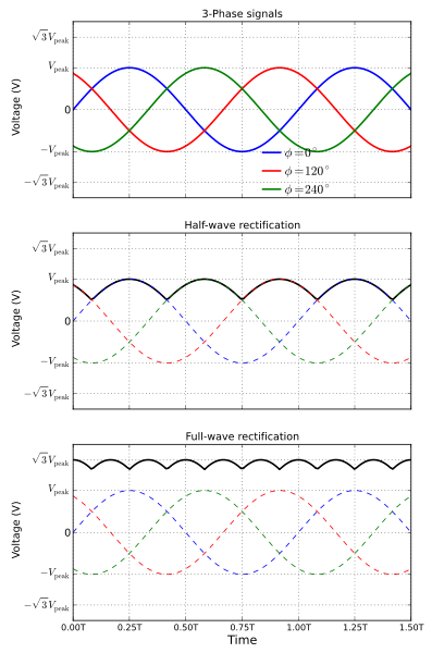
The result in a very high effective DC output voltage with limited ripple. That's why it gets dumped right into the aircraft buss with only the small capacitor located inside the alternator All the diodes are working all the time and they don't "take turns" in sequence. Each diode is rated at 50A continuous and the three phases are actually additive, overlapping sine waves. Take away a phase by removing a winding and you will generate less amperage. The output from this configuration is about 1.73x the peak phase voltage and I extrapolate that to be directly proportional for current also. See the diagram attached for reference. Therefore, I calculate each phase only needs 19.5A (100A over 3 phases divided by 1.71) to produce 100A output. That 19.5A maximum per phase is far less than the 50A rating we're discussing and suggests a large margin exists. Realistically, 100A units are run somewhere less than 100% max continuous load calculations which suggests even more margin is built in.
Having said that, the unit described is typically use for high output amperage truck alternators in the 90A range and you can do your own research to verify the applications. You might also want to check the diode sizing in the TCM 60A alternator to see how that compares with the 50s I replaced those with.
Your last comment seemed to suggest some form of risky behaviour was being contemplated by this thread. Some nonsense about night IFR or whatever. I think it was unnecessary and a pointless addition to what was intended to be an informative discussion.
Paul
Legacy, Calgary
(where my steady state draw at night is 12 amps)
I wouldn't feel quite that confident in the replacement diodes. The stator current flows in series through 2 diodes at any given time and the current cycles between the diodes as the alternator rotates. So for a portion of the time a given diode will be passing 100% of the current - but not all the time since they "take turns." I don't know how the diode package was rated, but I think the 50-amp rating is marginal for a 60-amp alternator. Given that, the alternator will rarely, if ever, be asked to deliver a full 60 amps, and there is certainly some margin built into the diode rating. And the rating is a function of operating temperature, so if the alternator stays cool, it's better. If you could find a diode assembly rated at 60 amps or more it would be a good thing. The 50
amp assembly will probably work okay, though. It's just not 50A X 6 = 300A. And if you routinely fly IFR at night with everything turned on and lit up....well, that's up to you.
Gary Casey
The diode assembly was sourced at my local shop with a spare set of brushes for $20 total. These are 50A diodes (50A x 6 diodes) which is a robust replacement satisfactory for even the 100A alternator. I had to remove the B+ stud from the old diode assembly and press it into replacement diode package. The re-assembly took about 20 minutes and it fired up with 10A charge on low engine idle. This is much higher charge at low idle than I can ever recall.Paul