Brent,
Always appreciate your insight (please
comment on text below if in error somewhere).
I do have Hugh MacInnes book and looked at
your reference.
Page 19 primarily refers to turbines not
compressors (although both use A/R as a common specification dimension).
It was my understanding that, what is primarily
changed between a .5 and .6 A/R compressor on our birds is the Radius (Area is
essentially unchanged).
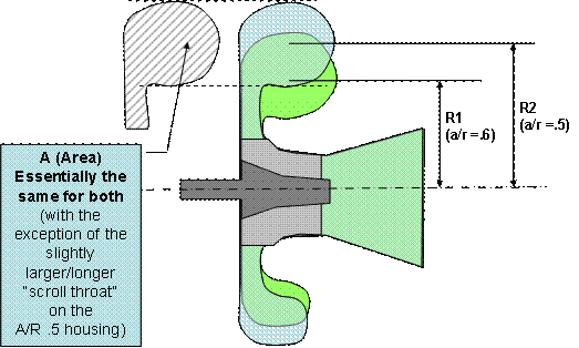
Ref Figure 2-15 in the book on page 19 (re-created
below) - note the housing Radius changes, but the output cross sections area
(and impellor) are essentially unchanged.
Area (A) is the cross-sectional area of the
compressor output. Since we all use the same silicon rubber connector sleeve
and aluminum tubes that connect the compressor output to the intercoolers, we
all have essentially the same “A” on our compressor outputs (with
the exception of the slightly larger/longer compressor back plane throat on a
higher “R” housing). My understanding was a .5 A/R compressor
housing was physically a bit larger because the radius of the scroll was
increased (as shown in fig 2-15 and below as R2 in blue).
My understanding is that A/R of the
compressor is not nearly as critical (sensitive) to performance as on the
turbine. As I understand, various A/R ratios on turbine housings are
typically indicative of the Area changing (turbine inlet throat size). Smaller
A = more turbine power, but also more engine exhaust back pressure. On
the turbine, a smaller “R” (other things equal) is also a marginal impediment
to mass flow (versus a larger R), but also allows the turbine to develop more
power – due in-part to the angular velocity/momentum of the fluid
entering the turbine (pin-wheel effect). Thus, typically the turbine
housing radius is as small as possible/practical (relative to the Area of the
turbine inlet and diameter of the expeller). Thus, turbine A/R ratio
variation is typically determined by inlet Area geometry variations (R being
held to the practical dimensional minimum for any configuration).
Likewise, it seems obvious that a compressor
with a smaller A (outlet area) would generally flow a smaller volume and/or create/sustain
a higher pressure ratio (other things equal and with other performance spec
impacts) relative to a similar compressor with a larger A. However, I’ve
never fully understood “why” Radius and A/R ratio (with Area held
constant as shown below and assumed in our installations) has much effect on
compressor performance (apparently based on some other articles I’ve read,
it doesn’t). Most books/articles I’ve found (including Hugh MacInnes’s)
don’t really address this. I have others like Gordon Oates
(Aerothermodynamics of Aircraft Engine Components), that are quite technically
detailed – but primarily deal with axial flow (common) jet turbines.
Others like http://ntrs.nasa.gov/archive/nasa/casi.ntrs.nasa.gov/19930091893_1993091893.pdf
deal with turbo/engine sizing assuming the performance of a set of available
pre-designed compressors that are otherwise fixed. Likewise, Charles
Taylor (engine god http://www.amazon.com/Internal-Combustion-Engine-Theory-Practice/dp/0262700263/ref=sr_1_3?s=books&ie=UTF8&qid=1291739980&sr=1-3
), does not do turbo design any real justice in his texts. There are some
other old NACA compressor design papers I have yet to read/research (now in
process).
Perhaps the compressor R effect has to do
with the rate of change in angular velocity/momentum of the fluid flow (from
longitudinally, to circumferentially to laterally). With a smaller “R”,
the apparent rate of directional change of flow vector is higher, which perhaps/probably
has subtle effects on the compressor map/performance. If so, this would essentially
be the appropriately opposite reason of why R is important on the turbine
housing – the added effect of incoming angular momentum of the fluid flow
imparted to the turbine blades (i.e. pinwheel effect), in addition to the classic
expansion effect of the fluid through the turbine. If so, I would perhaps
expect a compressor with smaller R (larger A/R ratio) to generally have a slightly
higher surge line (more pressure at lower flow rate, on the compressor map, i.e.
higher pressure ratio – other things equal), due to the fact that the
fluid flow vector is generally more aligned to the impellor movement (angle of
attack) and would also have a harder time flowing 180 degrees backwards against/through
the compressor impellor vanes (low R) vs just 90 degrees (higher R) (angles exaggerated
for clarity). This of course would likely/probably come at the expense of
mass flow performance, no free lunch.
Also, I’m not aware if the Piper A/R=.5
compressor and std TCM-TSIO-550 A/R=.5 compressors use the same compressor
impellors. I understand the overall impellor dimensions are the same, but
it seems the actual impellor vanes (often incorrectly referred to as the
impellor Trim) could be different (in count and/or shape/profile). It
seems that would/could have a significant difference on the compressors performance
characteristics. More research needed???

Rick
From: Lancair Mailing List [mailto:lml@lancaironline.net] On Behalf Of Brent Regan
Sent: Tuesday, December 07, 2010
7:42 AM
To: lml@lancaironline.net
Subject: [LML] Re: Inquiry:
Critical Turbo Altitude (LIVP) with TSIO550E?
Rick Writes:
<<<
For anyone who might not have caught/understood this…
I believe, the Mirage .50 A/R is a larger turbo/compressor housing
(as expected). A/R = Area/Radius of the output scroll. Similar
output connector area, larger scroll/housing radius. <snip>
Rick>>>>
Compressor housings for a given model of turbocharger are designed to be
interchangeable and therefore have nearly the same R (Scroll Radius) so
describing a turbocharger as "bigger" can be misleading. What is
important to keep clear is that a higher A/R ratio (0.60) will cause the
turbocharger to run slower and produce less boost (pressure ratio) than a lower
A/R (0.50) which will cause the turbocharger to run faster and produce more
boost. If you don't believe me then read page 19 of Hugh MacInnes' book
"Turbochargers".
Regards
Brent Regan