“Soldered stranded wires will
eventually break off if soldered, it makes a shear point.
If you need further proof I would
suggest you convince yourself. Do an experiment. Solder the wire to the
connector. Wiggle it up and down. With the connector fixed to something hard
so it won't move.
See how fast it breaks.
Now do the
same with a crimped connection. If using an un-calibrated tool, play with the
force you use to crimp the wire. This will allow you to form your own opinion.”
But it may not be a well informed
opinion. Please consider the following and then you can make a somewhat better
informed decision.
The observation above makes an interesting
secondary point, but it is only SECONDARY. Keep in mind that many military/aerospace circular connectors have solder
cups on the back of pins already in place, so clearly under some circumstances solder
joints are acceptable even in these industries. But as noted in prior
discussion, the key is not the solder or crimp joint, but rather the quality of
the execution. It is easier to crimp and get a high quality joint than to
solder and get a high quality joint, but that does not mean solder is out of
the running.
The PRIMARY point in getting a
reliable termination is to make sure that there can be NO RELATIVE MOTION
between termination and wire – no flexing, no vibration movement,
nothing, nada, zip.
Wiggling is forbidden! Otherwise
the termination will likely fatigue and fail sooner or later. You can get away
with lousy workmanship and practices in stationary installations, but in
aircraft where there is vibration or (sometimes more important) cable flexure
arising from working with cables in the aircraft (maintenance induced
failures), it is more important to make sure there can be no relative motion
between wire and termination. Crimp versus solder controversy is secondary.
BOTH can be made to work satisfactorily, and more reliably than a connector.
This is the key. Both rely on NO RELATIVE MOTION to ensure continued joint
integrity.
Shift your focus for a moment from
the termination to the STRAIN RELIEF, the thing on the connector aft of the
termination that clamps onto the wire bundle. It is there to carry the
mechanical loads from the wire bundle to the connector shell, and to entirely
eliminate any relative motion between wire and
the termination, be it crimp or solder. No strain relief, no reliability. THE
STRAIN RELIEF IS AS IMPORTANT AS THE WIRE TERMINATION, maybe more so. Note
that the strain relief clamp has to clamp tightly onto the cable. This may
require adding diameter to the wire bundle; most commonly with silicone self
stick tape, to get good clamping action on the wire bundle. Here is an
example.
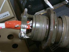
Note that the wire bundle is small
so the tape is used to increase the diameter, and coincidentally minimize the
chances of the clamp cutting into a wire if it is over tightened. Note also
that the wire shields (from twisted pair shielded lines) are connected to the
cable shell for maximum noise protection as suggested in some equipment
installations. Follow equipment installation instructions when it comes to
handling shields.
But the ideal is to connect wires WITHOUT
connectors to eliminate the potential fallibility of the connector. The goal
is to approach the reliability of a continuous wire in a wire run. You can do
this with crimp connections or solder connections. Either must be properly
executed to achieve the desired level of reliability, that is, better than a
connector.
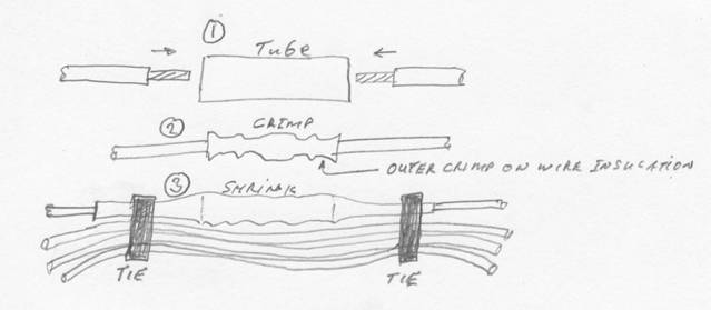
The most common crimp connection for
wires is with the little tube. Put a stripped wire end into the tube, then
crimp. But you are not done. Now you need to stop relative motion between
wire and crimp. Shrink tubing over the entire thing helps, but frequently shrink tubing that fits over the
tube is too large to close tightly over the wire to stop the relative motion.
And the shrink tubing is not as rigid as a cable clamp. So better is to
shrink, and then tie both ends of the connection beyond the tube crimp
connector to the bundle to get some rigidity and stop the potential relative
motion.
The problem is that a bunch of
these tubular crimps and shrinks can lead to a big bulge if you are connecting
a lot of wires in a bundle as from panel to airframe. You can end up with a
bundle that looks like the python that swallowed the rabbit. And this
normally occurs where space is at a premium.
The place you really get screwed is
if you have to separate the wires and then reconnect. Your only option is to
cut the wire where it enters the tube crimp connector, and you lose some
length. Better have some spare length somewhere!
The same result can be achieved with
a solder connection which can later be separated with no or minimal loss of
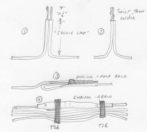
wire length for subsequent reconnection. The steps are as follows:
1)
Include
some spare length in the wires to be connected. This allows for later
disconnection and reconnection which may require cutting the soldered portion
of the wire and re-stripping.
2)
Strip
about ½ inch or more off each wire.
3)
Twist
the wires getting at least three twists to make a good mechanical connection
between wires.
4)
Solder
the twisted pair.
5)
Shrink
tubing over the joint AND some wire insulation.
6)
Fold
the connection back against one or the other of the connecting wires.
7)
Shrink
tubing (next larger size) over the entire junction.
8)
Tie
into wire bundle.
The resulting joint prohibits
relative motion between the two wires at the junction. Mechanical forces are
transmitted through the wires and through the outer shrink tubing when you mess
around with the wires subsequently, and then all is locked down when the bundle
is tightly pulled together and then anchored somewhere.
This solder method yields a
connection that can be as virtually as reliable as the unbroken wire, which
means it is more reliable than a connector. The joint can also be smaller than
a completed crimp connection, and by staggering the joints along the wire
bundle length, the rabbit in the boa constrictor bulge can be largely avoided.
Crimp enthusiasts can use this same
technique if using the single ended crimp caps or cups instead of the solder
joint. The trick is to find these in small diameters. You won’t find
them at a hardware store which stocks only the big ugly stuff for 10 gauge wire
used by house electricians.
So, some may prefer crimp
connections (which require a bit less skill, but still require a good crimper
that can deliver a double crimp, one on metal and one on the insulation, so ya’ll
strip and insert and crimp carefully!) and some may prefer solder. Both
require that the subsequent joint be immobilized to assure that there will be
NO RELATIVE MOTION between wire and termination. Both can be made to work
reliably, but both require attention to detail to be most reliable.
Key notes:
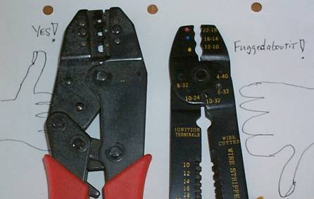
1)
As
noted previously, use high quality crimpers. For connecting wires to one
another be sure to use racheting crimpers that will not release until the job
is done. For my crimpers, this frequently means squeezing with both hands to
get the damn thing to release, but then the joint is well and truly crimped. The
photo below shows an OK crimper and a junk crimper. Throw away the junk
crimpers.
2)
If
you decide to use crimpers, go with gold plated pins wherever possible. FOR
SURE use gold (or silver plated pins on some coax connectors) on low level
signal lines from transducers and on antenna lines. The voltage levels on
these lines are down at the microvolt or millivolt level. If you use a
non-gold plated connector, a thin molecular layer of metal oxide between mating
parts is enough cause an open circuit and error. Fourteen or twenty-eight
volts is enough to punch through the thin oxide layer, so cheaper tin plate
connectors (like some Molex connectors) are marginally acceptable on these “wet
contacts,” but for signals from pressure transducers, flow meters, fuel
tank sensors, etc. tin plate connections are not reliable enough in “dry
contact” applications and can develop a very thin film of corrosion. Particularly
in humid areas, the low voltage can not punch through the oxide layer. It won’t
happen this year or next, but becomes more likely with the passage of time.
3)
When
troubleshooting sensors and antennas, start by disconnecting and reconnecting
connectors. The wiping action cleans the contacts, and may restore the
integrity of the connection.
4)
Pay
attention to detail.
Before we quit, let’s go back
to fundamentals. Why do you want connectors between panel and airframe in the
first place? To ease subsequent troubleshooting? I fully understand the pain
of working behind the panel, particularly with a steeply sloped windshield as
on the Lancair. Let me suggest another alternative – a simple panel
hinging method. See below.
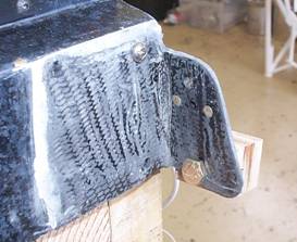
I tried the piano hinge behind the
panel anchor point, but was not satisfied. It was a pain to get holes aligned
because my panel is already assembled and hard to handle. So some
brainstorming with a friend yielded the solution above.
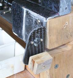
1) Cut the lower flange off the
anchor point on the panel. Its absence is visible in the photo on the right
where the flange used to occupy the slot in the wood stand.
2) Build a carbon flange onto the
panel. I already had the attachment holes drilled, so I put 4 BID on the
front, then drilled through the carbon from behind, then put 2 BID behind and around
the flange, and drilled through this from the front to preserve the hole
locations. Extend flange down below bottom edge of the panel where it bends
around parallel to the fuselage.
3) Drill a ¼ inch pivot hole in the
flange even with or slightly below the bottom edge of the panel so that the
panel can rotate down without interference.
5) Make up a phenolic block thick
enough to span the distance from flange to fuselage wall. Drill and tap ¼-28
6) Install panel, grind phenolic
blocks to match sidewall of fuselage, then flox the blocks in place and align them
while the flox cures by putting in a ¼-28 bolt of appropriate length. The panel
can now fold down about 60 degrees from horizontal as long as your wire service
loops are long enough. Don’t forget to disconnect struts and other
anchors before flipping down! Have a pre-cut piece of wood with foam to hold
up the panel when folded out, or use a cable to suspend it from the roof.
7) The forward portion of the
armrest ahead of the stick needs to be removable to allow the panel to fold
down. That is why I have the anchor nut on the top of the flange as shown. The
armrest will anchor here and on the sidewall when installed.
Fly safely.
Fred Moreno