To the impatient,
First, much thanks to George,
Walter and Tim for an extremely informative presentation and facility tour. Special thanks to Mike for organizing
the un-organizable Lancair special interest community – those hot heads that
want cooler heads.
The basic thrust of the
presentation:
Under the assumption that enough
cooling air is present and adequately departing the bottom cowl, the
presentation focus was on making sure that the cooling air was passed thru the
cylinder head fins. The majority of
the heat is generated at the top couple of inches of piston travel – thus one
must pay attention to using all of the fins at the top (upper) portion of the
cylinder to dissipate the heat generated in the cylinder. Remember that there are conditions that
affect how much heat is generated by the combustion event, FA ratio, peak
pressure timing, power, etc. Again,
this discussion will be directed to making the engine baffling work to maximize
heat removal by making the available air reach all the cooling fins.
The following also assumes that
the cooling is top down with the engine in a tractor configuration. A primary difference between Continental
and Lycoming is that the valve push rod tubes are on the cylinder bottom for
Continental and the top for Lycoming thus making some bottom baffling
requirements more challenging for the Continental (in my opinion).
A) Many baffle setups do not
completely route cooling air around the fins on the lower portion of the
cylinder even though they look pretty from above.
B) Some arrangements for other
uses of cooling air (intercoolers, oil coolers) may block or create low pressure
areas that rob the cylinder head of adequate airflow.
C) Both Lycoming and Continental
cylinders have a “flat” side that does not allow air to flow to the lower fins
because of the baffling, except at inter-cylinder locations.
D) Some cylinder locations can be
super-heated by infrared radiation from the exhaust stack and the impact is
fourth order as the temperature of the exhaust increases. This condition must be examined for
appropriate shielding.
Yes, readers will have to remove
both the upper and lower cowling to evaluate the performance of their
baffles.
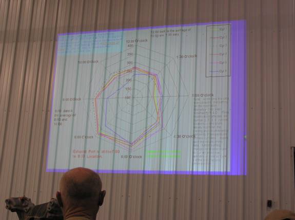
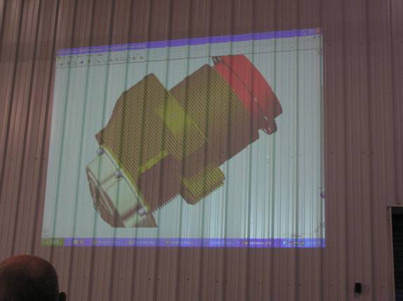
The slide below depicts measured
cylinder head temperatures (I don’t have the notes on exactly what the
conditions were) around the cylinder for various cylinders (Bonanza). Note the
temperature spread around the cylinders and the difference between some. CHT probes are located at the cyl bottom
– seemingly the hottest location.
Also, note that more even cooling around and between the cylinders would
be less stressful on the engine.
Specifics for (A):
The picture below (blurry that it
is) shows a baffle addition with a fence to better direct air to some bottom
fins. It is your job to figure out
what cylinder it is for. This
typifies some of the cylinder areas that have to be examined.
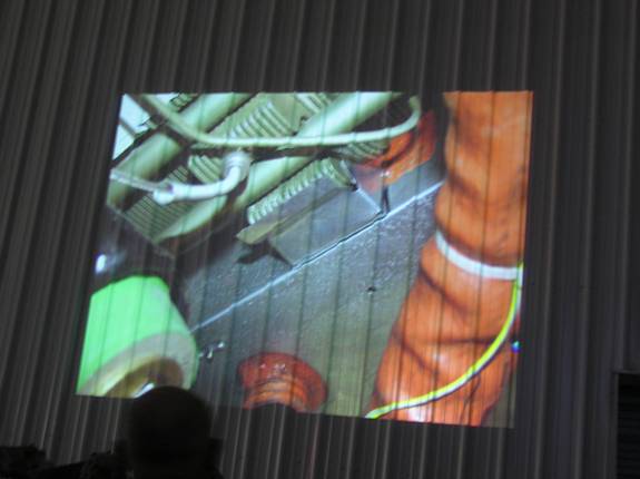
Specifics for (B):
The oil cooler below deflects a
great deal of cooling are over the top of the cylinder behind. One recommendation would be to put a
“curved wing” about 3/8” above the top of the cooler to direct some air flow
down to the face of the cylinder.
Another problem depicted below is
the creation of a low pressure area near the cylinder because another air flow
user is drawing off a great deal of air.
George Kool-Aide Braly tried a scoop (or roof) behind the cylinder to
direct air down but says that did not work because of the low pressure. Instead he built a vertical fence along
side the intercooler that was baffle sealed to the upper cowling and extended
just forward of the necked down part of the intercooler. Cylinder cooling was restored.
Specifics for (C):
The above picture also
demonstrates the problem described in (C).
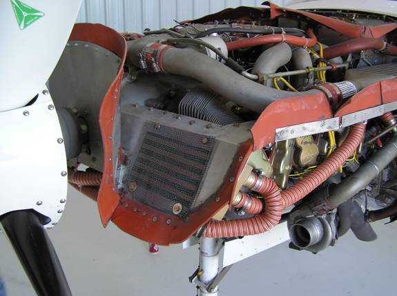
Below shows the “flat spot.” This is troublesome on the fwd right cyl
and back left cyl on the continental engine and the fwd left and back right (??)
on the Lycomings – at least it is on my 4-cyl 320. Troublesome because air cannot pass from
above the spot to below without some baffle work.
The picture below shows an
additional hole to get air to the lower baffle although George recommends a
“roof” (maybe even with sides) is used to direct the airflow down.
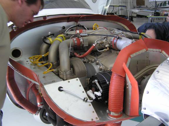
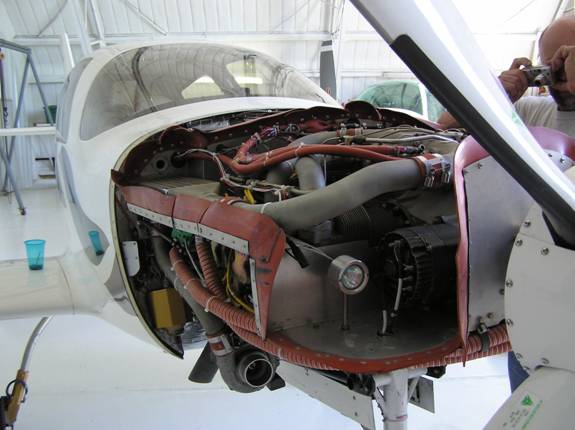
See the opening? See it behind the B-lead terminal on the
alternator? Two pix back one could
work that in below and behind the landing light.
I hade modified my 320’s cyl two
baffle to better allow air to the fins at the lower front quadrant and cyl 2 is
no longer the hottest. Maybe I can
get a picture of that mod posted soon.
It is time to fix the baffling behind cyl 3 to cool that one better
also.
Specifics for (D):
Darn, no picture! When you look underneath the engine, you
will see that some baffle extension will be needed on fins adjacent to the
exhaust port. It is useful to
enclose the extension with full side walls to ensure the air doesn’t spill out
before cooling the fins. Another
benefit is that the side nearest the exhaust also becomes a radiant heat shield
so the fins aren’t additionally heated by the nearby exhaust pipe. The exhaust system should be examined
for where radiant heat may affect components, including the cylinder head. Some things can be shielded with
aluminum on the “thing” or a stainless steel standoff shield may be attached to
the exhaust pipe with a SS hose clamp.
It’s a beginning. Good luck and stay cool.
Thanks again to George, now known
to me as Mr. Kool-Aide from Ada.
Requires hot and cold running air.