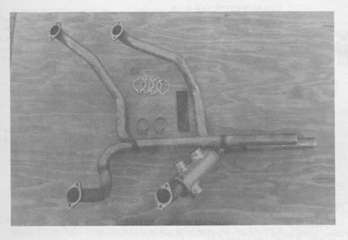
In a message dated 10/31/2003 9:55:40 PM Central Standard Time, marv@lancaironline.net writes:
<<<I have a device on my number one exhaust pipe (Lycoming 320) to heat air and
distribute it to the cabin and carb heat. It has three ports, one small and
two larger ones. Does anyone know how it is supposed to be oriented. I can't
make any sense out of it.>>>
Bill,
I don't know why someone else hasn't answered this question but I am sure you understand that ingenuity is required here just as much as with other parts of any Lancair project.
I had a muff built for me by the very same folks (Snow?) that built the exhaust pipes (Type V, muff on cyl #4) for my injected engine. It has only two 1.5 inch openings located at opposite ends and about 180 degrees from each other. Input air was tapped from the baffle floor in front of cyl #2 and routed to the bottom front of the muff. Heated air comes out the top back of the muff and is routed to the side entry of the cabin heat valve (pilot side firewall) and thence into the cabin or out the front, depending on the valve position. The waste hot air is routed, via SCAT tubing, to exit near the cowl air outlet.
Since you have a carburetor, one of the large openings is to collect input air, generally from the baffling floor above it because fresh air (non-engine compartment, no CO) is needed for the cabin heat function. The other large opening is used to feed hot air to the carburetor air box, therein selectable as "carb heat". these are the larger openings because the unfiltered hot air may become the only engine air source (ice clogged filter?). The smaller opening is the cabin heat air, used as noted in the prior paragraph. The orientation of the muff will fall into place based on the position of the cowling components.
Trivia Question: Why was a type V exhaust, designed for an injected engine, equipped with a "carburetor heat" muff?

Scott Krueger
Sky2high@aol.com
II-P N92EX IO320 Aurora, IL (KARR)