|
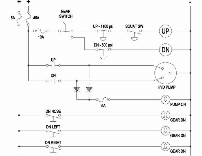
Attached is a diagram of my planned Legacy
"Electraulics" (great word). Note that for maximum safety, the diodes
should be attached directly to the relays and the fuse holder, if possible, 2
keep the wires as short as possible and routed in such a way as they cannot
short out to ground or each other. Therefore, the fuse needs to be at the
pump/relays and not up on the panel. Crimp ring terminals to the
diode leads and shrink wrap the diode and leads from terminal to
terminal. Leave nothing exposed. MARK THE POLARITY OF THE DIODE
SOMEWHERE YOU CAN SEE IT AFTER IT IS SHRINK WRAPPED!
I'm actually intending to use LED's instead of
incandescent lights and also have gear up indication, push to test for the
LED's and other stuff so the circuit will be a little different to
accommodate that.
The 10 amp breaker in front of the gear switch is
probably excessive. My 320 had 5 amp (I think - I didn't build it) and I
sometimes had problems with it not pulling in the relay. Not a fun feeling
to NOT hear that pump run when you put it in the down position! FYI - the
relays are automotive style "solenoid" relays. They can draw a few
amps.
Also, the 5 amp breaker/fuse for the indicator
lights may be excessive but, like I said above, I'm doing other things -
"Electraulics" related - with this circuit. I suggest you don't put
anything non-gear related on any of these circuits - just my opinion.
I must say, I was very hesitant to post this as the
"Mad Dogs" on this site are sure to rip it apart! :~)
R. Dan Ribb
L2K @
30%
www.eaa376.com/l2k


HydPumpElec.jpg
|