|
Interesting idea, Neil on the 180 deg reverse. The key, of course, is reducing the worst noise components while minimizing gas flow restriction. Reversing gas flow direction might imped gas flow more than necessary. The mufflers I made were very quite - like I mentioned. You could be at the wing tip and not hear the engine idle but I could get full power on take off. Unfortunately, while everyone that heard it compared to previous muffers agreed it was much quiter, never got around to actually measuring the noise level.
Good luck, hope you get the time to experiment with it, would love to know your results.
Ed
------ Original Message ------
Sent: 11/24/2019 3:48:27 PM
Subject: [FlyRotary] Re: Mufflers
ED,
What you did reminds me of a paper published in OZ
many years back, where the "expert" suggested that all that was
required to stop the pulses was to "Rub" the exhaust along a tube
to even out the pulses. What he designed was a muffler with many
internal 180 degree bends that sent the gas many feet by "rubbing"
against the wall of the tubes in the 180 bends. Your design is
the same principle as the swirling effect is rubbing the gas
against the wall of the pipe. Your two 2.5 inch pipes amount to
an approx single pipe of 3.75 ". So a 4 " pipe would be even
bigger. Back pressure?? can only be measured by a manometer
possibly?
The idea is very interesting and I wonder if the gas was reversed
at each "turbine" ( the washers direct the gas in opposite
direction each time) would help to quieten the noise even better
or faster meaning less washers ( weight) and back pressure?. So
many unanswered questions that can only be answered with
experimentation and time. My "you beaut" decibel meter may
actually get some use if it actually works.
Thanks ED and if I can find time will experiment with black steel
to start with.
Neil.
Sorry, Neil,
Been a while, it was two exhaust pipes, one for each exhaust
port. Mistyped, error on the drawing the disc were 2 1/2" dia
inside a 2 1/2" dia pipe. The discs fit snugg enough that when
one broke loose and spun on the rod, it scored the inside of
the exhaust tube. I got the discs from McMaster Carr. Try
oversize SS washers. The tubes were actually glass pack
mufflers which had 2" dia inlet/outlet. I cut the front off and
then after inserting the discs use wide metal clamps to put the
tube back together (welding would of course have been better).
I do not believe that any of the dimensions are critical
except the discs should fit touching the inside of the tube if
possible. I called them discs but they were actually oversize
SS washers with a hole in the center for the rod. I ended up
with 5 discs inside each tube. I used the spacing for the
shorter 36" long tube. The idea was to have a large portion of
the shock wave dissipated inside each segment of the tube while
keep the gas flowing freely.
It was truly quite and like I mentioned I could get 6000 rpm
with my 13B on take off. Large diameter tube/discs would likely
permit more/easier gas flow, but since I can not weld, just
finally gave up and went on to other things.
Ed
------ Original Message ------
Sent: 11/23/2019 10:35:27 PM
Subject: [FlyRotary] Re: Mufflers
Ed,
On rereading your post, am I correct in
believing that you had one pipe per exhaust? A total of 2
pipes? How many discs were in each pipe? I may have
misunderstood, but you say you had a 2.5 inch disc fitted
inside a 2 .125" exhaust pipe. If correct measurement how
did you manage to force 2.5 " inside 2.125" pipe? perhaps
the other way around measurement wise?
Thanks, Neil.
Given the recent interest in mufflers, I thought I
would throw in my experience with home made muffer. I
could hit 6000 rpm on take off with my 13B with the
2.18:1 Gear ratio. You could stand within a wing width
with the engine idling and bearly hear it. At 6000 rpm
it was about 1/2 as loud as an unmufflered lycoming.
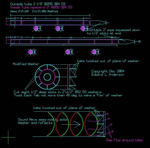
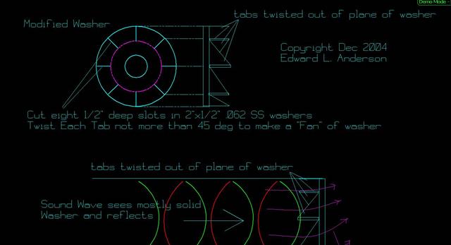
The basic idea was to break up the shock wave while
minimizing gas flow impedeance. I used 1/8" thick 2"1
/2 Dia stainless steel disc inside of a 2 1/8" dia
stainless steel tube. The disc has slits cut from the
outer edge approx 1/2" toward the center in 8 regions
as shown in the diagram. Then each "tab" was twised
45 deg from the plane of the disc. If you looked at
the disc front on it look almost as a solid disc with
just a small slot area showing through. The idea was
that the shock wave would basically see a "solid or
mostly solid" disc where as the gas could still flow
through the slots around the tabs. I had a threaded
rod extending the length of the tube with jam nuts on
each side to hold the disc in place.
The reason for the rod and nuts was not being a
welder- I used jam nuts - welding it turns out would
have been much better as the nuts eventually became
loose. That was not good, when one of the disc came
lose it started to spin and greatly impeded the gas
flow. Although folks told me it sound cool - like a
turbin winding up.
In any case, I decided that not being a welder
there was no way I could remedy the defects. I think
if there were some way to "spot weld" the outer part
of the tabs to the tube and perhas to a rod in the
center the muffler would have extend it useful time.
I flew approx 12 hours
including one trip to Tracy Crook (first extended
flight with muffler) by the time I got there at least
one disc had broken loose and was spinning. Tracy was
kind enough to use his welding skills to weld the
discs to the rod on one of the mufflers (had two one
for each exhaust), but within another 6 hours or so
disc in the other muffler started to spin. Also I
found that the shock wave pounding eventual would
break off a tab or two since they were not anchored
and could flex.
Just thought I would throw the idea out there in
case it has any merit.
Best Regards
Ed
bnownp1a.jpg
22gpummc.jpg
|