Thomas,
Referring to Monty's initial response I'd agree
with most of his comments except #6, "look at hot day takeoff and climb. size
max opening for that." I'd recommend look at hot day takeoff and climb, size 10
- 20% larger than what you think is required for that. In my opinion its
easier/better for early flights to start out too large and have excess cooling
than to start too small and possibly have an emergency or engine damaging
situation on your hands on your first flight. For optimum performance it will
require revision either way, but too big is less stressful during early flights.
Its probably easier to shrink an inlet or outlet than to stretch
one.
As for your design, I understand the desire to
start with a proven, engineered design. I'd bet that Monty is correct and there
there was a lot more trial and error in the P-51 design than any of us realize.
As for copying that design, I have two issues and I know I've stated this before
so sorry for sounding like a broken record:
1) The shared inlet for both oil and water, while
it looks better/cleaner, I doubt it is any more aerodynamically efficient. Using
two entirely separate paths (in my opinion) will make troubleshooting and/or
modification easier if either system tends to run too hot.
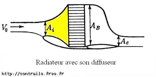
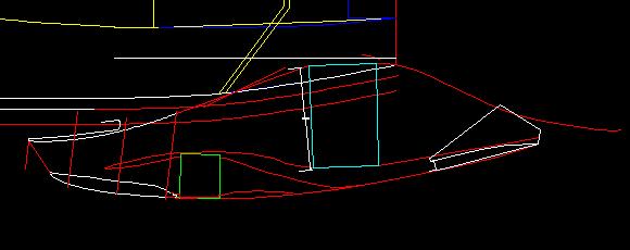
2) The configuration you are using (at least as
depicted) demands a relatively thick radiator with a relatively small frontal
area. I know several people have tried this approach - I'm not aware of any that
were successful. A thick radiator using modern tube and fin construction is
simply too restrictive to airflow. I believe current thinking
is that a thin radiator with lots of frontal area is better from both a
cooling efficiency and a drag reduction viewpoint. Even if the airflow has to
make several 90 degree turns to get through the core. At one point I had some
data from a cooling system engineer who used to work for GM to show this, but
that info is long since lost.
Mike Wills
RV-4 N144MW
Sent: Friday, January 29, 2010 9:32 AM
Subject: [FlyRotary] Re: Tiff to CAD Software
Ben,
This
is a Long-EZ Hybrid so, yes the cruise speeds will be much higher than the
Cessna style high wing designs.
As
far as the amount of effort involved ……… I would have to say that you get out of
it what you put into it.
I
started with this:

…..
and now I’m here:

My
original post was to share a tool that I constructed to convert a graphics file
to a CAD drawing to allow it to be manipulated. Once I have a final version of
it, I’ll add it to my website for download (for those
interested.)
T
Mann