|
|
Al Gietzen wrote:
Ernest; since you were first to propose the internal airflow, or vane; what would you think is the appropriate shape, position, etc. I can understand your non-participation on the ‘other’ list after being labeled “completely and totally wrong”. (That’s what you get for not reading his book J ).
That didn't bother me. He got my goat when he bounced the email where I referred him to Chapter 12 of K&W that analyzes the inefficiencies of the layout he proposed. Claimed I didn't 'sign' the email. I may not know a lot, but I've got sense enough to listen to those who do (and I decide who does knows a lot by testing what they say). I'll contact Paul when I want to know how to use Rhino.
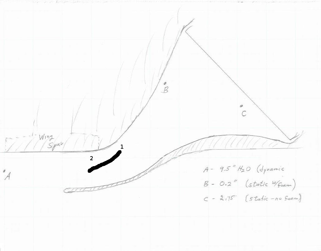
There's still not enough data to put hard numbers on it. For that, we'd need to know exactly where the separation occurs (somewhere around point 1) and how thick the boundary layer is at point 2. The way I like to think of it is that you have tired air at point 1, and it just gives up trying to make the turn. The air below point 2 is still strong, so blow some of it into the area at that point. But, if you pull to much of the strong air, then the air at C will be to tired to make the turn. It's a balancing act. You'd need a good CFD program to make the optimal decision, so quit trying 8*)
You've got nearly enough cooling, you just want a little more, so do it the easy way. Attach a couple pieces of angle to the bottom of the duct to act as standoffs (or just use the existing supports). Bend a piece of aluminum to have legs, and that will stretch between the standoffs. Cut adjustment slots in the legs. Install it maybe/sorta/kinda like the line I drew and go fly a few patterns to see if it improves. Add a few more pressure measurement points if it is convenient, and keep track of the angles and distance from the spar. I'd want 4 simultaneous static measurements across the face if possible, biased towards the top and bottom. Keep the diverter well back inside the duct, unless you want to test what happens when you bring it further forward. Beat a curve into the aluminum if you think it will help. It'll only take a few flights to understand what the diverter is doing, and if it helps or hinders progress. Once you're happy, add a couple more bolts/screw/rivets to lock the diverter in place, or make a permanent one out of glass'n'goop.
The line with the slight curve is what I would try first, with the emphasis on 'first'. You may be completely ecstatic with the first attempt and not care to experiment further. I'd want to play. Flying all those patterns would be tedious if you want to take a lot of measurements, so consider sticking a leaf blower or three in a sealed box with an opening that you can tape over the cooler's entrance. I'd draw a diagram of the diverter's orientation next to a graph of the pressure measurements to be able to visualize how the pressures are changing as I move the diverter around.

OC scoop.jpg
|
|