|
|
Dave here are the photos I have. If I hit the limit I will send in separate messages. First is article on building and using a dyno. The dyno described is not the same as the one in the photos but the info is transferable. Jerry
Building a low cost dyno.
Revision 2
By Paul Lamar
Wouldn't it be wonderful if everybody developing an engine for use
in aircraft could afford a dyno. It would be a lot safer if people
tested their intended engine for horsepower and static thrust on the
ground instead of during the first flight.
STATIC THRUST
HP needs no introduction. Static thrust is that amount of force we
get out of the engine, speed reduction unit (if you have one) and
prop combinations that causes the airplane to initially accelerate.
Acceleration is defined as a change in speed. What we want is
maximum change in speed in the minimum amount of time so we can get
up to takeoff speed in the shortest distance.
IT IS NOT JUST A GOOD IDEA
Isacc Newton laid down the law for this sort of thing over a hundred
years ago. He said acceleration is proportional to force divided by
weight. Simple enough. More force more acceleration. It is not just
a good idea it is the LAW! If the force is divided by the weight in
pounds we get a measure of the acceleration in units called "G's".
One G is a change in speed of about 22 MPH in one second. If the
static thrust (force) equals the weight, our airplane will be going
22 MPH the first second and 44 MPH after two seconds. The average
speed for the first second is only sixteen feet per second so we
will have traveled down the runway only sixteen feet. At the end of
the next second our average speed is thirty two FPS plus sixty four
FPS divided by two seconds or forty eight feet FPS. We are now
ninety six feet down the runway and going 44 MPH. You see how
important static thrust can be. The more the static thrust the
better. One G is a wonderful acceleration. If only the average
airplane had thrust equal to it's weight. Unfortunately the real
world is not that wonderful or simple.
PROP PITCH
The thrust from the engine may increase or decrease as we travel
down the runway depending on several factors the most important of
which is prop pitch. If we have a fixed pitch prop and our pitch
chosen is so high that the engine cannot spin the prop at max HP RPM
while the airplane is stopped (typical for most fixed pitch prop
airplanes) our thrust may increase as we accelerate down the runway
and as the RPM comes up to max HP. If we have a constant speed
propeller the thrust will will start out at the max possible and
gradually decrease as we accelerate along the runway. Never the less
the airplane will takeoff quicker with a constant speed propeller as
we are getting more average HP out of the engine.
MEASURING HP & STATIC THRUST
HP is merely the product of torque and prop RPM. We can measure the
torque by mounting the engine and prop combination on something that
is free to rotate about the prop shaft axis. If we restrain this
rotation and measure the force on a lever arm we will know the
torque. If we allow the test stand to move forward and measure the
force to restrain that motion we will know the static thrust.
BUILDING A DYNO
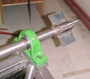
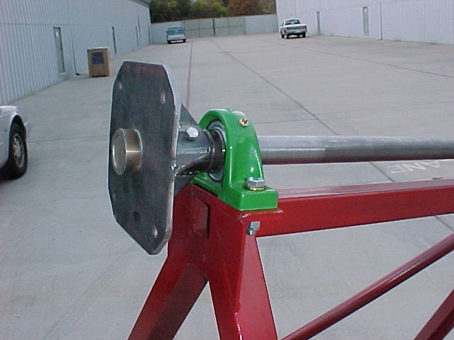
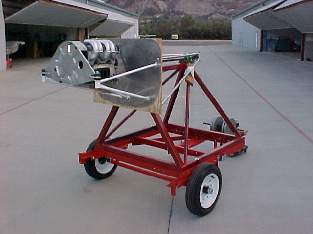
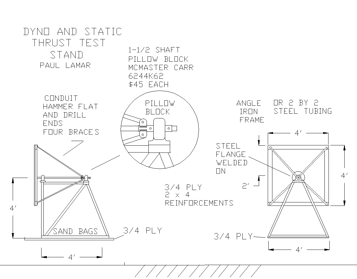
You can build a low cost dyno from a junked car rear axle, bathroom
scale, ground adjustable prop and garage door spring to check HP and
static thrust. Make a two by four and three quarter inch plywood
frame about four feet high to hold the rear axle. Bolt the frame
together with 3/8 carriage bolts and three inch drywall screws.
Fabricate a two by four reinforced plywood firewall and bolt it to
an old steel wheel. The wheel provides stiffness and a means to
attach the firewall/wheel assembly to the axle. Take out the pinon
gear and one axle shaft to reduce friction and leave in the
differential spool for it's inner axle bearings.
MOUNTING THE ENGINE
Mount the engine with the motor mount you intend to use in the
airplane to the firewall. Install the cowling to minimize the slip
stream drag and improve the accuracy of the static thrust
measurement. Mount the axle about four feet off the ground with a
wide base two by four wood frame work. Streamline the frame work
with styrofoam or thin sheet metal. Mount some cheap wheels or
casters on the frame work to allow fore and aft motion. The axle
allows the firewall to rotate about the prop axis. Stop the rotation
with a two by four lever arm. Attach a streamlined two by two
compression strut to the end of the lever arm and rest it on the
bathroom scale. Make sure the strut is on the left side when the
prop is rotating clockwise from the pilots perspective. Attach the
base of the bathroom scale to the 3/4 inch plywood shelf. Attach a
block of wood on the top of the scale to prevent the compression
strut from blowing off the scale. Best have some positive means of
limiting axle rotation to plus and minus twenty degrees in case
something goes wrong. Attach the garage door spring to the opposite
end of the axle and to a large tree or other suitable anchor. Use
some sand bags to weigh down the whole rig to keep it from rolling
over when blipping the throttle.
CALIBRATING THE DYNO
Calibrate the torque system with a large torque wrench. With a two
foot lever arm double the scale reading to get foot pounds of
torque. Calibrate the garage door spring using water as
calibration weight. See my article on this subject in the Feb. 98
issue.
TESTING
Mount the engine and PSRU with an adjustable pitch prop. Balance the
rig about the axle shaft so the engine does not rotate on it's own
and zero is showing on the bathroom scale. Run the engine up to max
RPM allowed by the pitch chosen. You now know the torque and prop
RPM so the HP can be calculated. Stop the engine and lower the
pitch until the engine will run at max HP RPM. Usually around 5000
RPM for a geared engine and around 2500 RPM for an aircraft engine.
You now know the max HP. Repeat this process for any RPM of
interest. Check the garage door spring for length and compare that
to it's calibration numbers. You now know the approximate static
thrust. The installed static thrust may be slightly more due to the
better streamlining of the complete airplane.
OPTIMIZING THE PROP PITCH
If you are using a ground adjustable fixed pitch prop you may
optimize it for the takeoff/cruise compromise by choosing a pitch
that causes the engine to run several hundred RPM below peak power
and twenty or thirty pounds below peak thrust. The engine will then
rev up during takeoff. Hopefully to peak power for climb.
MEASURING FUEL CONSUMPTION
Make a fuel consumption gage out of a long piece of clear plastic
hose mounted vertically. Measure how much fuel the hose will hold
between marks using a chemistry lab calibrated beaker. Time the fuel
consumption with a stop watch. Use an electric pump and an on/off
switch to fill the hose again to repeat the fuel consumption test.
Don't forget to correct for the temp. of the fuel. You now know the
gallons per hour and the BSFC can be calculated from that
information and the HP. Brake Specific Fuel Consumption or BFSC is a
measure of the efficiency of the engine. It is in units of pounds of
fuel burned for each HP for one hour. A good number for an aircraft
engine is .42 pounds per HP hour. Some car engines are about .45 to .
55. Hook up a manifold pressure gage and record that as a function
of HP. Knowing manifold pressure is very important to be sure your
engine is developing the maximum possible HP at any RPM.
I highly recommend bulding this dyno as it is better to find out on
the ground what your engine prop combination is capable of rather
than during the first flight.
ENGINE HP VERSES TORQUE AND PROP RPM
PROP |--------------- TORQUE in Lb/Ft --------->
RPM 100 120 140 160 180 200 220 240 260 280 300 320 340 360 380 400 420
--------------------------------------------------------------------------
1000 19 23 27 30 34 38 42 46 49 53 57 61 65 69 72 76 80
1100 21 25 29 33 38 42 46 50 54 59 63 67 71 75 80 84 88
1200 23 27 32 37 41 46 50 55 59 64 69 73 78 82 87 91 96
1300 25 30 35 40 45 49 54 59 64 69 74 79 84 89 94 99 104
1400 27 32 37 43 48 53 59 64 69 75 80 85 91 96 101 107 112
1500 29 34 40 46 51 57 63 69 74 80 86 91 97 103 108 114 120
1600 30 37 43 49 55 61 67 73 79 85 91 97 104 110 116 122 128
1700 32 39 45 52 58 65 71 78 84 91 97 104 110 116 123 129 136
1800 34 41 48 55 62 69 75 82 89 96 103 110 116 123 130 137 144
1900 36 43 51 58 65 72 80 87 94 101 108 116 123 130 137 145 152
2000 38 46 53 61 69 76 84 91 99 107 114 122 129 137 145 152 160
2100 40 48 56 64 72 80 88 96 104 112 120 128 136 144 152 160 168
2200 42 50 59 67 75 84 92 100 109 117 126 134 142 151 159 167 176
2300 44 53 61 70 79 88 96 105 114 123 131 140 149 158 166 175 184
2400 46 55 64 73 82 91 100 110 119 128 137 146 155 164 174 183 192
2500 48 57 67 76 86 95 105 114 124 133 143 152 162 171 181 190 200
2600 49 59 69 79 89 99 109 119 129 139 148 158 168 178 188 198 208
2700 51 62 72 82 92 103 113 123 134 144 154 164 175 185 195 206 216
2800 53 64 75 85 96 107 117 128 139 149 160 171 181 192 202 213 224
2900 55 66 77 88 99 110 121 132 143 155 166 177 188 199 210 221 232
3000 57 69 80 91 103 114 126 137 148 160 171 183 194 206 217 228 240

dyno-aft.jpg

dyno-detail.jpg

dyno-SZP.jpg

Dyno4.gif
|
|